21-year-old pre-op ECG for traumatic fracture. What does this ECG show?
- Dextrocardia
- Ectopic atrial rhythm
- High lateral myocardial infarction
- Right Axis deviation
- Limb lead reversal (Wrong lead placement)
The right answer is:
5- Limb lead reversal (Wrong lead placement)
Explanation:
Whenever you see upright P-QRS-T in lead aVR, you should immediately suspect limb lead misplacement. The QRS axis might not be necessarily positive if the axis was deviated. However, the upright P and T waves (subtle in this ECG) should be alarming. Especially when you see the typical aVR wave morphology present in another augmented lead (in this case aVL).
Quick guide to spotting LA/RA reversal
- Lead I is completely inverted (P wave, QRS complex and T wave)
- Lead aVR often becomes positive
- There may be marked right axis deviation.
Quick guide to spotting LA/LL reversal
- Lead III is completely inverted (P wave, QRS complex and T wave)
- The P-wave is unexpectedly larger in lead I than lead II (it is usually the other way around)
Quick guide to spotting RA/LL reversal
- Leads I, II, III and aVF are all completely inverted (P wave, QRS complex and T wave)
- Lead aVR is upright
To understand the rules of how to make this recognition, you will need to understand 4 concepts about how the ECG machine works AKA applied physics.
Applied physics trivia 1: ECG is a voltmeter/galvanometer
You might be familiar with the diagram in figure 1 from your study of physics years ago. A Voltmeter (V) here is measuring the voltage difference between 2 points (A and B) in this simple battery and bulb circuit.
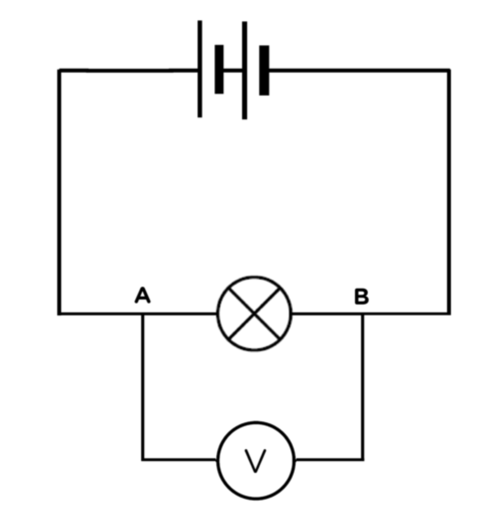
Figure 1: Voltmeter/galvanometer in a simple battery and bulb circuit.
Applied physics trivia 2: Three basic laws of electrocardiography
The direction of the wave drawn by the ECG (Voltmeter) depends on the direction of current in relation to the positive electrode (Figure 2).
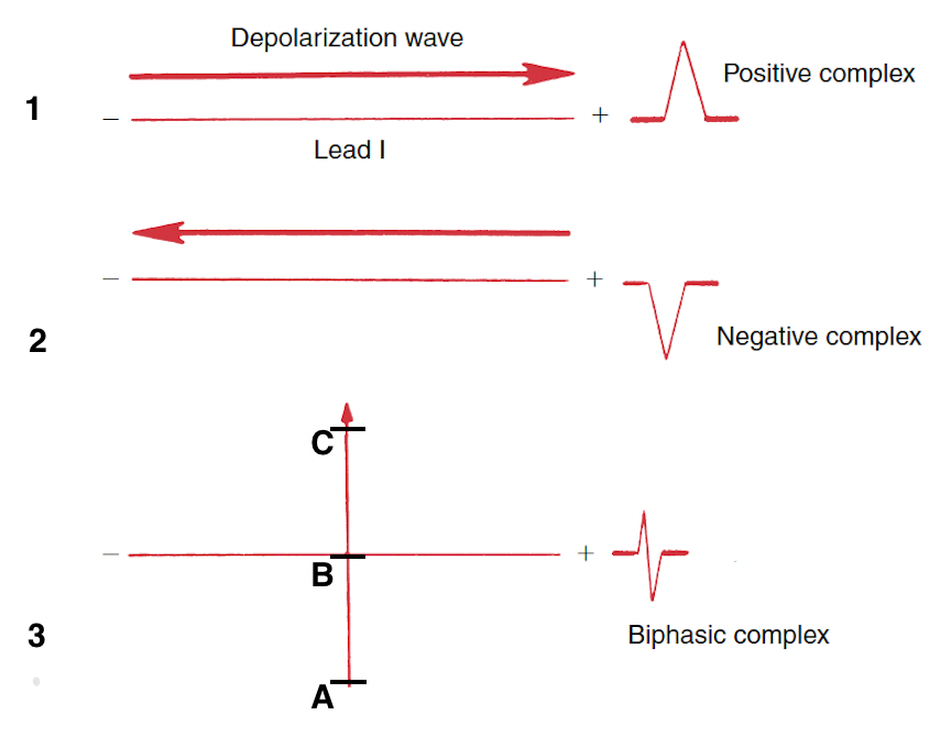
Figure 2: 1, A positive complex is seen in any lead if the wave of depolarization spreads toward the positive pole of that lead. 2, A negative complex is seen if the depolarization wave spreads toward the negative pole (away from the positive pole) of the lead. 3, A biphasic (partly positive, partly negative) complex is seen if the mean direction of the wave is at right angles (perpendicular) to the lead. The positive electrode considers Point B to be closer to it when compared to point A, so as the electrical current moves from point A to B the positive electrode draws a positive wave as it senses the wave moving closer to it. Meanwhile Point C is further to the positive electrode when compared to point B and hence, as the electrical current continues beyond point B, the positive electrode reads the current as moving away and subsequently draws a negative wave. These three basic laws apply to both the P wave (atrial depolarization) and the QRS complex (ventricular depolarization).
Applied physics trivia 3 / History trivia 1: The 12 leads are just different cameras that record the same game from different angles at both horizontal and frontal planes / Evolution of ECG leads
The Bipolar limb leads: The ECG leads introduced by Willem Einthoven consisted of 4 electrodes connected to the 4 limbs with the right leg electrode being electrical ground. The 3 bipolar limb leads were made using those limb electrodes' measurements and represented voltage difference between the 3 limbs. They were called bipolar limb leads as each lead only involved 2 electrodes. When the electrocardiograph records lead I, the LA (Left Arm) electrode detects the electrical voltages of the heart that are transmitted to the left arm while the RA (Right Arm) electrode detects the voltages transmitted to the right arm. Inside the electrocardiograph, the RA voltages are subtracted from the LA voltages, and the difference appears at lead I. When lead II is recorded, a similar situation occurs between the voltages of LL (Left Leg) and RA. When lead III is recorded, the same situation occurs between the voltages of LL and LA. So, electrocardiograph machines were programmed to subtract the negative (reference) electrode voltage from the positive (exploring) electrode voltage. The negative (reference) and positive (exploring) electrodes are defined and standardized for each lead by the machine. This relation can be represented schematically as in figure 3.
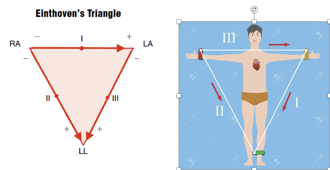
Figure 3 Orientation of leads I, II, and III. Lead I records the difference in electrical potentials between the left arm and right arm. Lead II records it between the left leg and right arm. Lead III records it between the left leg and left arm.
Einthoven’s triangle can be redrawn so that leads I, II, and III intersect at a common central point.
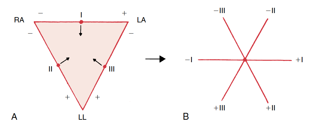
Figure 4: A, Einthoven’s triangle. B, The triangle is converted to a triaxial diagram by shifting leads I, II, and III so that they intersect at a common point.
The augmented limb leads: Emanuel Goldberger invented the three augmented unipolar extremity leads: aVR, aVL, and aVF. The abbreviation (a) refers to augmented; (V) to voltage; and (R), (L), and (F) to right arm, left arm, and left foot (leg), respectively. Augmentation refers to voltages recorded by the electrocardiograph being augmented 50% over the actual voltages detected at each extremity electronically inside the electrocardiograph to make the waves more readable. The last letter in the lead name (R, L, and F) refers to the positive (exploring) electrode while the negative (reference) electrode is the sum of voltages of the other 2 electrodes which would represent a point halfway between these 2 electrodes. Hence, those lead vectors can be estimated as in figure 5.
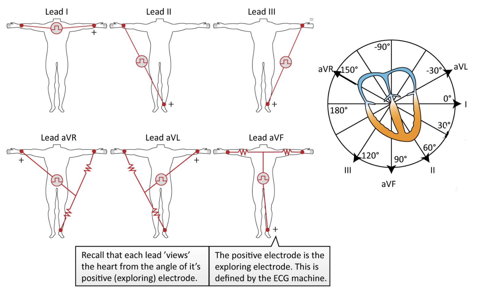
Figure 5: the derivation of all 6 limb leads The hexaxial reference system: All leads can be combined into a hexaxial diagram that shows the relationship of all six limb leads (right side of figure 5).
Applied physics trivia 4: One plus Three equals Two
The bipolar leads are related by the following simple equation:
Lead I + Lead III = Lead II
In other words, add the voltage (e.g. R wave voltage) in lead I to that in lead III and you get the voltage in lead II. It is a good practice to scan leads I, II, and III rapidly when you first look at a mounted ECG. If the R wave in lead II does not seem to be the sum of the R waves in leads I and II, this may be a clue that the leads have been recorded incorrectly or mounted improperly. Einthoven’s equation is simply the result of the way the bipolar leads are recorded; that is, the LA is positive in lead I and negative in lead III and thus cancels out when the two leads are added:
I = LA − RA
III = LL − LA
I + III = LL – RA + (LA – LA) = LL – RA = II
Thus, in electrocardiography, one plus three equals two.
Spotting limb lead reversal
LA/RA reversal
With the reversal of the LA and RA electrodes, Einthoven’s triangle flips 180 degrees horizontally around an axis formed by lead aVF.
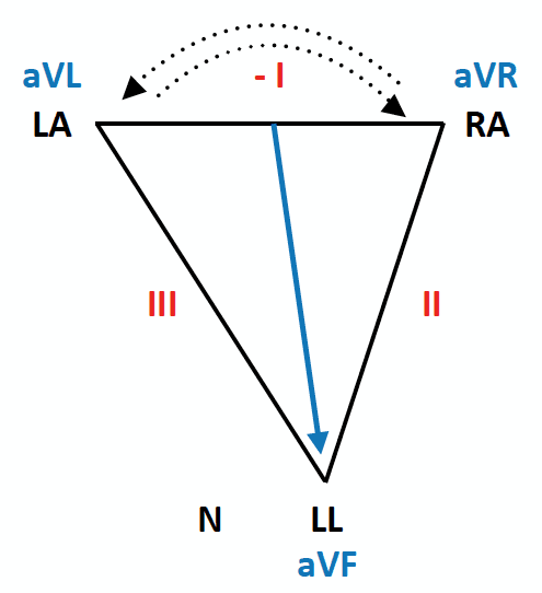
Figure 6: RA/LA reversal
This has the following effects on the ECG:
- Lead I becomes inverted
- Leads II and III switch places
- Leads aVL and aVR switch places
- Lead aVF remains unchanged
LA/RA reversal may simulate dextrocardia. However, in contrast to dextrocardia, there is normal R wave progression in the precordial leads.
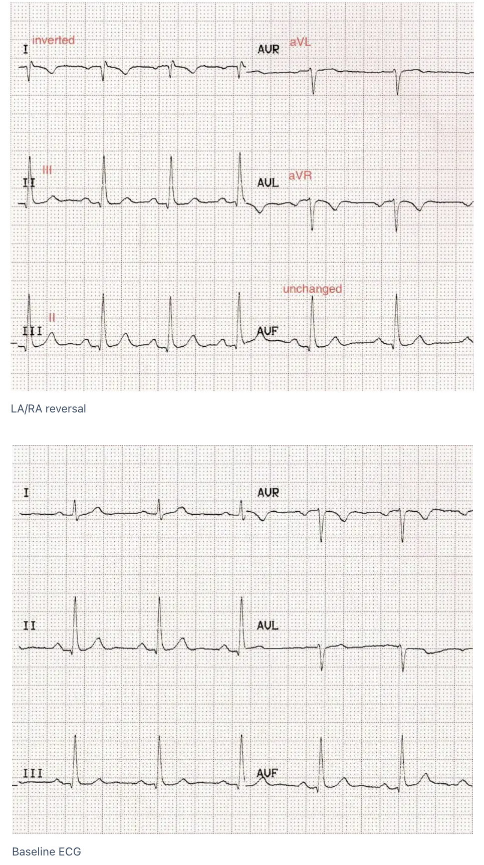
Figure 7: LA/RA reversal ECG
LA/LL reversal
With the reversal of the LA and LL electrodes, Einthoven’s triangle rotates 180 degrees vertically around an axis formed by aVR.
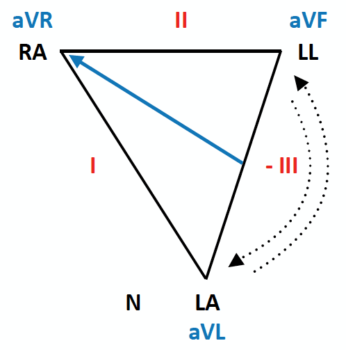
Figure 8: LA/LL reversal
This has the following effects on the ECG:
Lead III becomes inverted
Leads I and II switch places
Leads aVL and aVF switch places
Lead aVR remains unchanged
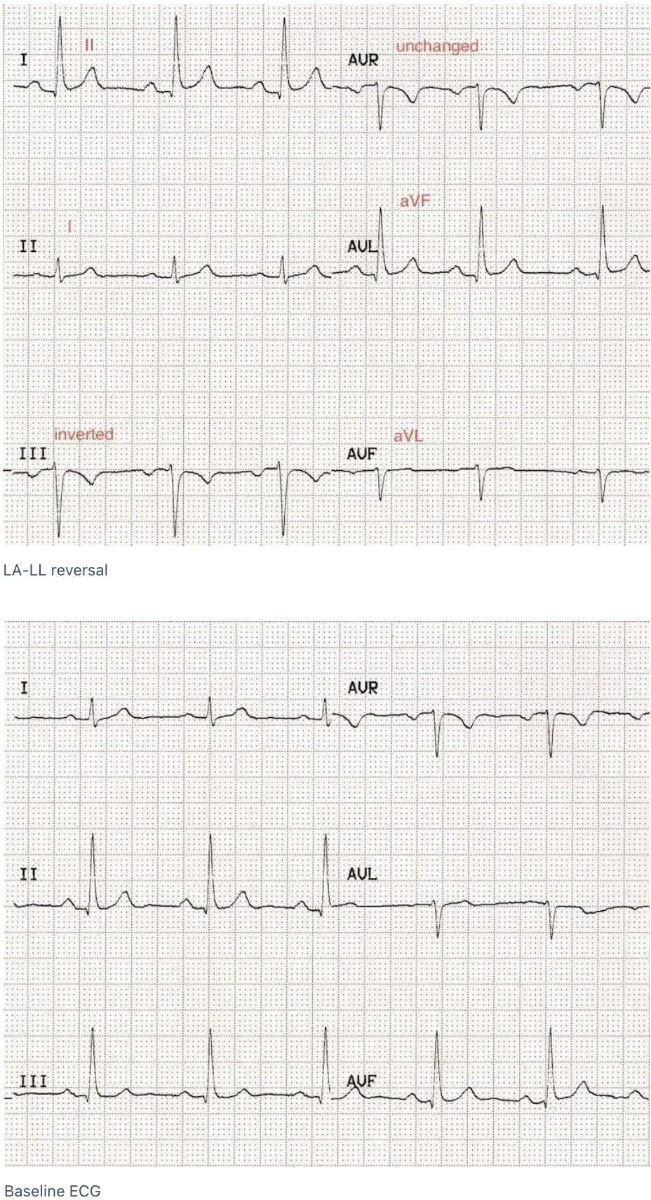
Figure 9: LA/LL reversal ECG
RA/LL reversal
With the reversal of the RA and LL electrodes, Einthoven’s triangle rotates 180 degrees vertically around an axis formed by aVL.
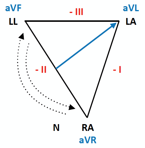
Figure 10: RA/LL reversal
This has the following effects on the ECG:
- Lead II becomes inverted
- Leads I and III become inverted and switch places
- Leads aVR and aVF switch places
- Lead aVL is unchanged RA/LL reversal Baseline ECG
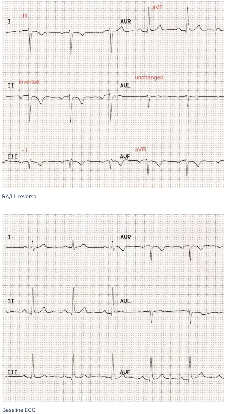
Figure 11: RA/LL ECG
References:
- Goldberger, Ary L., Zachary D. Goldberger, and Alexei Shvilkin. Clinical electrocardiography: a simplified approach e-book. Elsevier Health Sciences, 2017.
- Clinical ECG interpretation. https://ecgwaves.com/topic/ekg-ecg-leads-electrodes-systems-limb-chest-precordial/#:~:text=An%20electrode%20is%20a%20conductive,created%20by%20analysing%20several%20electrodes.
- Ed Burns and Robert Buttner. Life in the fast lane. https://litfl.com/ecg-case-137/https://litfl.com/ecg-limb-lead-reversal-ecg-library/